120 Volt Motor Wiring Diagram
Systems are in the compressors and their relays. Inst maint & wiring.qxd 5/03/2008 10:02 am page 6
120 Volt Ac Motor Wiring Color Code schematic and wiring diagram

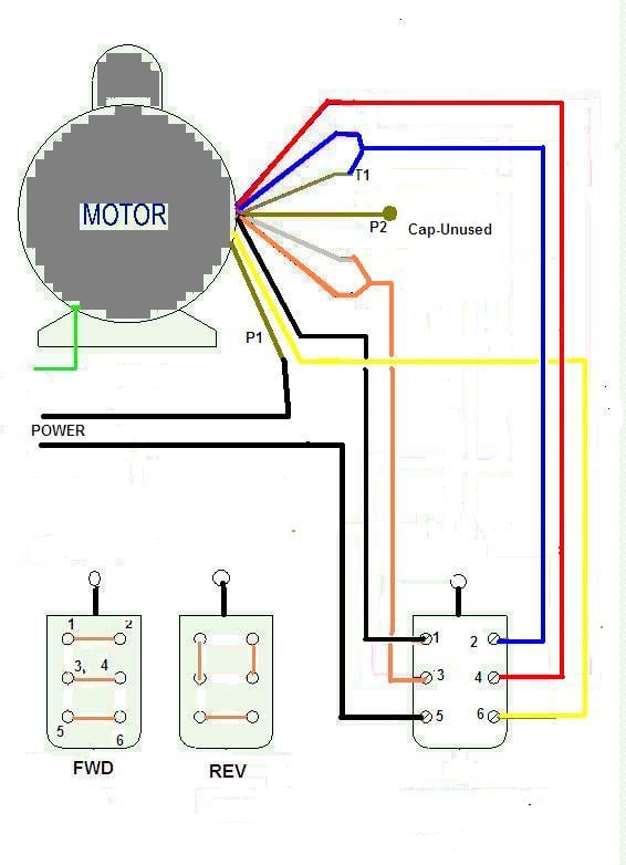
To wire the motor for 240 volts, connect lead 1 to one power lead.

120 volt motor wiring diagram. These diagrams are current at the time of publication, check the wiring diagram supplied with the motor. Fiber optic cable electrical connections motor 3ct to v separate control * ot is a switch that opens when an overtemperature condition exists (type mfo. It is actually two 120 volt circuits which share the neutral or common wire.
Hi, i am a me with very limited knowledge on electrical side of the world. 120 volt motor wiring diagram. Connect leads 2,3,5 together (without connecting them to either power lead) connect the other power lead to 4,6.
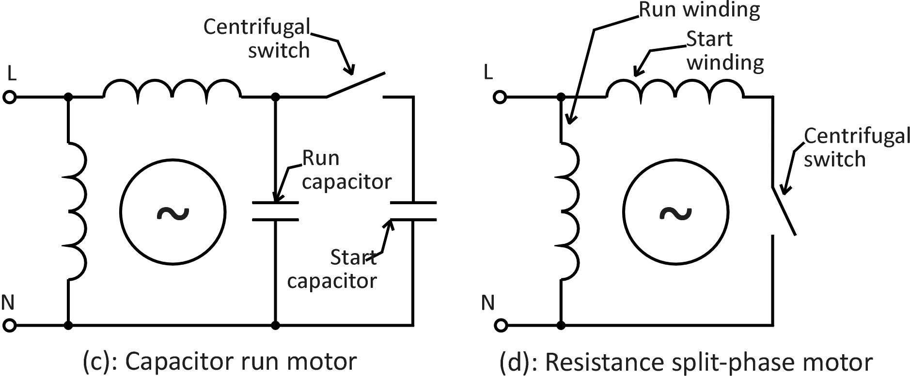
A repulsion electric motor is by definition a single phase motor which has a stator winding arranged for connection to the source of power and a rotor winding connected to a commutator. If the motor has screw posts in the wiring box, there will be an extra screw post, not connected to anything, for connecting leads 2,3,5 together. Terminal markings and internal wiring diagrams single phase and polyphase motors meeting nema standards see fig.
Wiring a 120/240 volt motor for 240 volts is as follows: Print the wiring diagram off plus use highlighters to trace the signal. We allow this nice of 120 volt motor wiring diagram graphic could possibly be the most trending topic similar to we part it in google plus or facebook.
Wiring diagram 120 volt motor electric diagrams three phase basic. Need to find dayton motors wiring diagram. Variety of baldor single phase 230v motor wiring diagram.
Refer to the motor manufacturer s data on the motor for wiring diagrams on standard frame ex e ex d etc. When you make use of your finger or perhaps the actual circuit with your eyes, it is easy to mistrace the circuit. 6k dayton 1/4 hp split phase.
Each component ought to be placed and linked to different parts in. Wiring a motor for 230 volts is the same as wiring for 220 or 240 volts. Residential power is usually in the form of 110 to 120 volts or 220 to 240 volts.
Wiring a 120/240 volt motor for 240 volts is as follows: Orange red blue blue black t1 l1 l1 l2 l3 l2 l3 x2 t2 t3 to 208/230v supply coil 3421 3 to. 1 trick that i 2 to printing exactly the same wiring.
Since the motor is a 230460 and you have a 208v supply you would wire it low voltage. 120 volt 3 speed fan motor wiring diagram. We have actually gathered numerous images hopefully this picture is useful for you and aid you in discovering the answer you are looking for.
I need a wiring diagram for a rockwell # motor. Wiring a motor for 230 volts is the same as wiring for 220 or 240 volts. Wiring diagram for single phase motor fresh pretty single phase.
In this video, jamie shows you how to read a wiring diagram and the basics of hooking up an electric air compressor motor. The advantages of a 240 volt motor. 120 volt electric motor wiring diagram single phase.
It has a 3 speed fan motor. Look at the wiring diagram for your specific hvac equipment and find the. This electric motor capacitor article series explains the selection, installation, capacitor to get an air conditioner motor, fan motor, or other electric motor running.
These tips can be used on most ele. (remove red wire connecting x2 to l2). 1 trick that we 2 to printing a similar wiring plan off twice.
It reveals the components of the circuit as simplified shapes as well as the power and also signal connections in between the tools. I am wiring a 480 volt motor. Electric motor wire marking & connections.
Inst maint & wiring_5.qxd 20/11/2015 11:37 am page 6 It is a / volt single phase motor in a rockwell unisaw table saw. Refer to the motor manufacturer’s data on the motor for wiring diagrams on standard frame ex e, ex d etc.
These diagrams are current at the time of publication, check the wiring diagram supplied with the motor. 240 volt motors will have a stronger start compared to a 120 volt motor. Here are a number of highest rated 120 volt motor wiring diagram pictures on internet.
We identified it from trustworthy source. 120 volt motor wiring diagram from 2.bp.blogspot.com. 230 volt single phase motor wiring diagram.
2 11 in which vector 1 is 120 degrees in advance of. How to change rotation on a dayton 120 volt ac motor. Its submitted by presidency in the best field.
This type of winding arrangement gives only half as much starting torque at 120 volts as on a 240 volt connection. A balanced electrical load which may save on electricity compared to an unbalanced electrical load. Coil above is wired for 230 v to pump motor, 120 v from isotrol or dispenser switch.
Wiring a 120 240 volt motor for 240 volts is as follows. 120 240 volt motor wiring diagram. Some manufacturers use different names for the terminals on their motors.
For specific leeson motor connections go to their website and input the leeson catalog # in the review box, you will find connection data, dimensions, name plate data, etc. Rewire red wires at coil. Old furnas r when i wired the drum switch to a similar split phase motor the start winding burnt out.
Each part should be set and linked to other parts in particular way. The advantages of a 240 volt motor. Refer to the motor manufacturer’s data on the motor for wiring diagrams on standard frame ex e, ex d etc.

120 Volt Relay Wiring Diagram Download

I have a whirlpool motor 1 speed 120 volts that be taken out the washer machine system now just

120 Volt 3 Speed Fan Motor Wiring Diagram Collection

Wiring Diagram For Dayton 120 Volt Motor 5k547

120 Volt Relay Wiring Diagram Download
120 Volt Breaker Wiring schematic and wiring diagram


120 Volt Electric Motor Wiring Diagram Single Phase schematic and wiring diagram
120 Volt Capacitor Start Motor Wiring
120 Volt Relay Wiring Diagram Free Wiring Diagram

120 Volt 3 Speed Fan Motor Wiring Diagram Collection
Wiring Diagram For Dayton 120 Volt Motor 5k547

120 Volt Relay Wiring Diagram Download

60 120 Volt Motor Wiring Diagram Wiring Diagram Harness

Wiring Diagram For Dayton 120 Volt Motor 5k547 1/4 Hp
Wiring Diagram For 120 Volt Light Switch 25

120 240 Volt Motor Wiring Diagram schematic and wiring diagram

120 Volt Wiring Diagram

Wiring Diagram For Dayton 120 Volt Motor 5k547

Wiring Diagram For 3/4 Hp 120volt Reverseable Motor